
https://www.dignitymemorial.com/obituaries/college-station-tx/terry-kohutek-5194499
Many years ago (1989, a third of a century ago), I was in an oral exam at TAMU; several civil engineering faculty were in the exam room.
Dr. Kohutek asked about a pin-supported frame subjected to a single concentrated vertical load:

- The frame itself is symmetric.
- Consider, he said, the load to be over the center of the beam; no sidesway deflection is expected — symmetry.
- Next he said, consider the load to be over the left column; no sidesway deflection is expected (due to flexural deformation).
- Next he said, consider the load to be over the right column; again no sidesway deflection is expected (again, due to flexure deformation).
- Now, place the load just to the right of the left column.
What is the expected horizontal displacement for this loading?
Which direction is the horizontal deflection?
I answered — incorrectly — that the deflection would be toward the left. Dr. Kohutek said the deflection would be toward the right. There was a vigorous discussion with more faculty saying left than right.
After the exam, Kohutek checked the answer using RISA (the first time I ever heard of the software). Of course, he was correct, it was his question.
I’ve been a bit bothered all these years, that I missed a question that was fairly easy to analyze but bothered also that the wrong answer seemed to prevail within the exam room (*). It certainly must have annoyed Dr. Kohutek.
In the PDF link, I present complete calculations:
- Calculation of the horizontal reactions at the base of the columns
- Calculation of the horizontal displacement at the beam level
- First, I determine the base reactions
 and
and  using the method of consistent deflections
 - Then I solve for
 using the method of virtual work.
 - In this specific example:
The column length is and the beam length is
All members are W8x24 steel beams
I place the 1 kip vertical load, , at one-sixth of the beam length
 - I also offer a graphical proof that the deflection is to the right.
See pages 17 through 20. - See the “Further Derivation” below for a closed form solution for
 such that
  is maximum
 - See the “General Solution” below for a closed form solution for
 For any frame geometry
 - As Vern Gosdin said, “That just about does it, don’t it”
Click for Asymmetric Frame Loading Calculations
Click for Influence Line
Comparison of horizontal displacement results:
| My hand calculation | Δ = 0.0384 inches |
| RISA-3D | Δ = 0.0387 inches |
| SAP2000 | Δ = 0.0383 inches |
as a variable,I derived
 in terms of :
![\[\boxed{\Delta_B=(1-2\beta)(1-\beta)\frac{\beta PL^3}{3EI}}\]](https://www.mathpax.com/wp-content/ql-cache/quicklatex.com-c3576d9295178f7d4da2ffe0d96dc639_l3.png "Rendered by QuickLaTeX.com")
 , and solving for
  where is a maximum or minimum:
 ![\[\boxed{\beta_{m}=\frac{3\pm\sqrt{3}}{6}}\]](https://www.mathpax.com/wp-content/ql-cache/quicklatex.com-b3ea112df82cc460d27e0eb3b621c692_l3.png "Rendered by QuickLaTeX.com")


Using the
value: ![\[\boxed{\Delta_B\text{ max}=(1-2\beta_{m})(1-\beta_{m})\frac{\beta_{m} PL^3}{3EI}}\]](https://www.mathpax.com/wp-content/ql-cache/quicklatex.com-2ef4b137a1743acebd344e7972e79d9c_l3.png "Rendered by QuickLaTeX.com")
is the height of the column, given in feet
![\[\Delta_B_{max}=0.032075\text{ }\frac{PL^3}{EI}\text{ feet}\]](https://www.mathpax.com/wp-content/ql-cache/quicklatex.com-5bad57f6dd921b99653e700b4b827121_l3.png "Rendered by QuickLaTeX.com")
![\[\Delta_B_{max}=0.3849\text{ }\frac{PL^3}{EI}\text{ inches}\]](https://www.mathpax.com/wp-content/ql-cache/quicklatex.com-bf45bdf7b4b7be753d580d78d4d42c73_l3.png "Rendered by QuickLaTeX.com")
 , which occurs when is located at
  . These values are in agreement with the influence diagram determined using RISA-3D.
In this general solution:
- First, I use the method of consistent deflections to determine the base reactions and
- Then I use Castigliano’s 2nd Theorem, to solve for .

The parameters are:
| Parameter | Example Value |
|---|---|
| : length of the beam |
24 feet |
 : length of the two columns in the bent frame : length of the two columns in the bent frame |
varies |
 : distance from left support to point load : distance from left support to point load |
4 feet |
 : distance from right support to point load : distance from right support to point load |
20 feet |
 : A/L : A/L |
1/6 |
| : B/L |
5/6 |
 : moment of inertia of beam : moment of inertia of beam |
I=307 for W12x40 |
 : moment of inertia of columns : moment of inertia of columns |
φ=1 |
| : area of beam |
A=11.7 for W12x40 |
 : area of columns : area of columns |
Θ=1 |
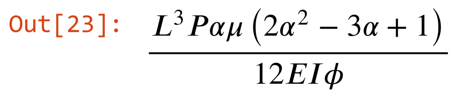
Click for General Formula calculations
Formula for deflection due to bending deformation in Cell 23
Formula for deflection due to axial deformation in Cell 30
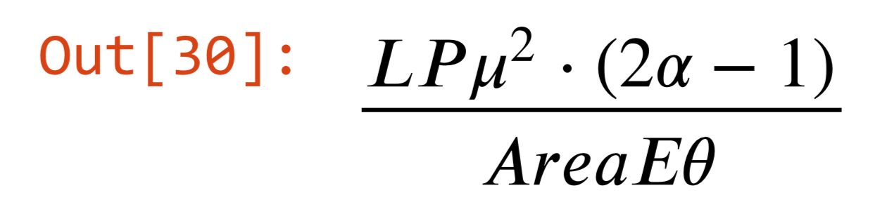
When the load is centered (at  ), both formulas go to zero, as expected for a symmetric loading. What might not be expected, is that a horizontal displacement is generated by loadings at the column lines (
 ). This horizontal displacement is solely the result of axial deformation in the columns.
Axial deflection along the beam
Bending deflection along the beam
Total deflection (axial + bending) along the beam
In the graphs, notice that there are 3 points specially marked along the beam; these represent the 3 alpha locations resulting in  . Refer to the general formula calculations.
In this specific example:
 ‘
‘
The column length is and the beam length is
Therefore, the column length is 12′ and the beam length is 24′
All members are W8x24 steel beams


