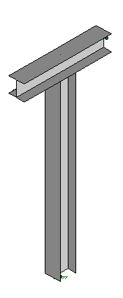
Let’s just start with a basic design:
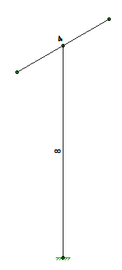
the tee is 8′ tall (bottom of base plate to top of steel beam)
the tee beam is 4′ wide
the steel column and beam are W8x31 (A992)
the tee beam is 4′ wide
the steel column and beam are W8x31 (A992)
any shorter and we would have used a W6x15 column and beam,
any taller or wider and the deflections under load would be larger
Now let’s document the BCs, the unit load deflections and the resulting k-factors
Axes and Boundary Conditions (BCs)
any taller or wider and the deflections under load would be larger
Y is vertical
The tee is in the YZ plane
X is out of plane and
X is the longitudinal axis of the supported pipe
The column base of the tee is fixed
Loading and Deflections
Givens:
The tee is in the YZ plane
X is out of plane and
X is the longitudinal axis of the supported pipe
The column base of the tee is fixed
One kip load in each axis direction
Load point is at end point of the tee beam (2′ out from CL column)
Load point is at end point of the tee beam (2′ out from CL column)
X axis deflection = 2.39″; k-factor = 0.42 kips per inch (mostly beam rotation)
Y axis deflection = 0.03″; k-factor = 33.3 kips per inch
Z axis deflection = 0.12″; k-factor = 8.33 kips per inch
Y axis deflection = 0.03″; k-factor = 33.3 kips per inch
Z axis deflection = 0.12″; k-factor = 8.33 kips per inch
Notice the very low stiffness in response to lateral load Fx
This is because the wide flange column has relatively small torsional stiffness
This is because the wide flange column has relatively small torsional stiffness


